Types Of Ship Vibrations – Hull Vibrations & Machinery Vibrations
Vibration in ships not only causes structural fatigue but also ruins the experience of the passengers as well as the crew due to discomfort. As a result, many of the ships are discarded if they cause too much vibration. It is because vibration in ships may indicate that there is something wrong with the functioning of the vessel and that it is probably unsafe to operate.
As the years went by, a lot of research went into the classification of these vibrations so as to locate the problem and solve it if possible. More importantly, changes have been made to the basic designing of ships to reduce the vibrations as much as possible. It not only makes the experience of the passengers and crew pleasurable but also increases the life span of the ship.
This article discusses general vibrations, ship vibrations and their classification, their causes, and the ways to tackle them in detail.
Before we dive into the classifications, let us take a look at the basics of how vibration occurs.
High school physics taught us that vibration is the motion of a body by which it is displaced from its state of equilibrium. Vibration can be ‘to and fro’ or ‘in and out’ or oscillation of a mass.
How Ship Vibrations Occur?
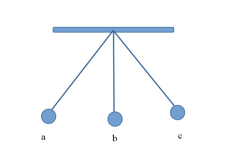
Let us take for example the above figure ‘b’ represents the state of equilibrium of the pendulum and ‘a’ and ‘c’ represent the oscillating positions of the pendulum. Thus, every time the pendulum is hit, it oscillates as it passes through the point ‘b’. Hence the conclusion that we draw from here is:
- An external force causes the vibration to start on a rigid body.
- The body is displaced from its stable equilibrium.
- Either gravitational force or elastic force causes the body to come back to its initial state of rest. This is known as the restoring force.
- Inertia causes the body to continue its back and forth movement.
- Finally, if no more external force is applied to it, the amplitude of vibration reduces gradually. In other words, the body slowly comes to a halt.
The phenomenon of vibration is dependent on the following four physical quantities:
- Mass [m]: The rigid body that is vibrating
- Spring [k]: The body’s elasticity
- Damper [c]: Means of energy dissipation
- Excitation [F(t)]: The system receives energy from excitation.
If any of the above is changed, the characteristics of the vibration will change correspondingly.
The number of independent coordinates required to represent the body of motion is called the Degree of Freedom (DOF). E.g., in the case of a spring-mass system, it is 1, and in the case of two spring two mass systems, it is 2.
Now that we know about the basics of vibration let us start with the classification. The classification of vibrating is mostly done based on the components causing the vibration. These are:
- Machinery Vibration
- Hull Vibration
Let us discuss these in detail one by one.
Machinery Vibration
Machines have moving parts, and these can cause vibration while operating. Such vibrations are called machinery vibration. Mainly, main engines, propulsion shafts, gearboxes, propellers, pumps, and diesel generators induce vibration.
Now that we know which are the parts that cause vibration, it becomes the duty of the engineer to maintain a safe level of vibration. These machinery vibrations may be further classified into the following three types:
- Torsional Vibration
- Axial or Longitudinal Vibration
- Lateral Vibration
Torsional Vibration
In general terms, torsional vibration can be defined as the angular vibration of an object along its axis of rotation. In a ship’s primary propulsion system, the main engine is connected to the propeller shaft. The shaft is made up of some smaller components.
The usual constituents of a marine shaft are the intermediate shaft and the propeller shaft which are connected with the help of coupling flanges. The presence of the connections like coupling flanges, thrust block, engine connection flange, and the cylinder-piston system in the main diesel engine creates torsion vibrations in the rotating shaft system. All of this causes ‘excitation’ naturally leading to vibration.
An engineer’s job is to design the shafts and discs and their placements in such a manner that the vibration in the main engine is below 5% of the natural torsional frequency of the entire propulsion system. In more technical terms, it can be put as the excitation should be minimized to prevent resonance. The resonance occurs when the vessel reaches a certain speed. Thereby, this speed is set as the barred speed range. As long as this speed range is avoided resonance will not occur. Torsional failure of the shaft may occur from the negligence of such limits and guidelines.
Axial or Longitudinal Vibration
The axial or longitudinal vibrations of the propulsion system are one of the most interesting cases of machinery vibration and also possibly the likeliest to cause vibration. It is necessary to identify the cause behind the vibration, to understand and analyze the vibration of a system. In the case of axial vibrations, the propulsion system acts as a mass system with multiple degrees of freedom working on a horizontal axis.
Let us take a look at the operation of the propeller in greater detail. The velocity of the water incident to the propeller blades determines the thrust generated by the propellers. It is known as ‘wake’. Since the hull has a curvature at the aft, the wake on the propeller is not uniform in nature. The wake on the top propeller disc is different from that on the bottom propeller disc.
This change is repeated with every revolution of the propeller. Thus, the thrust generated by the propeller is periodic. It is known as alternative thrust. This alternative thrust acts as the exciting force that results in the axial vibration of the propulsion system.
Mathematically speaking, propeller excitation is equal to the RPM of the propeller multiplied by the number of blades it has. So, the designers need to make sure that the first few natural frequencies are at least 5% away from that of the propeller excitation frequency so that any resonance can too.
Lateral or Transverse Vibration
In this case, the direction of vibration is perpendicular to the axis of the shaft’s rotation. In this structure, the intermediate and the tail shaft can be considered as beams while the shaft bearings may be regarded as the support points.
Because of the curvature of the shafts, the ideal centerline of the shaft and its center of gravity do not coincide with each other. Hence, when the shaft rotates its shifts away from the ideal center line because of the centrifugal force on the center of gravity. This results in a vibratory motion called whirling of shafts. The occurrence of this type of vibration is dependent on the number of shaft bearings and the distance between them.
While preparing the design the person should be careful that the natural frequency of the lateral mode of vibration does not coincide with the natural frequency of the engine because if that happens, there will be resonance which in turn would result in an extreme case of whirling. This would result in the shaft snapping and causing disastrous and damaging effects.
After starting the ship’s engine, the speed is gradually increased to a point where the vibration is felt maximum. It is known as the Critical Speed or Barred Speed Range. It is never advisable to sail at this speed. Even if this speed has to be reached for some reason, it should be passed as soon as possible. At this point, the RPM of the engine coincides with the natural whirling of the ship making it dangerous to continue at this speed.
Prevention of Vibrations
A ship designer must be well acquainted with the causes of the vibrations and make his designs accordingly to minimize the vibrations as much as possible. The primary reasons behind whirling vibrations have been stated below:
Propeller Fluctuating Loads
As discussed earlier, the effective thrust provided by the propeller is not along the shaft centerline. Instead, it is present at some angle to the center line of the shaft resulting in bending stress onto the shaft which in turn causes whirling. Also, as the angle between the thrust and the shaft centerline changes periodically, various modes of whirling are observed. To counter whirling, the propeller should be aligned in such a way that the effect is minimized.
Diesel Engine Excitation:
One of the primary sources of excitation for whirling are the moving parts in a diesel engine and the gas pressure in the engine. The radial components of it cause the whirling vibration whereas the tangential components result in the torsional vibration.
The manufacturers provide data related to the pressure exerted by the gas in the engines which is used to draw reference from while making the designs of the shaft.
Shaft Alignment Errors:
Sometimes the shaft coupling flanges are not properly coincided during the shaft alignment at the shipyard. It causes a loss in the continuity of the rotation axis of the shaft.
A similar coupling defect is noticed when all the coupling bolts through the coupling flanges are not correctly aligned. It results in the misalignment between the coupling flanges. Mistakes like these will excite the first mode of whirling excitation, and any shipbuilder should avoid these errors to maintain good shipbuilding practices.
Manufacturing Defects in the Gear System:
During the installation of the various gearing equipment, it might so happen that some of them don’t get installed properly. Under such circumstances, it is evident that high-frequency whirling will be generated due to improper gearing. This is something that needs to be taken care of at a very early stage, during the construction phase and it is not related to the vibration analysis of the design phase.
Longitudinal vibrations can be tackled in the following ways:
In such scenarios, there are generally two options. Either one has to change the propeller excitation frequency or has to alter the main propulsion system’s frequencies. Before discussing the processes any further let us take a look at the feasibility of each option.
The propeller excitation frequencies can be changed by either changing the number of propeller blades or by altering the RPM of the propeller. The former is not a practical option because the number of propellers has a lot to do with the efficiency of the propeller.
However, being so far into the design process the pre-decided RPM of the propeller cannot be altered either. This is because based upon the required torque and the thrust required to deliver effective power to the ship has already been decided upon and it is not a good idea to change all of this. So, these two options cannot be considered valid.
Hence, the option that remains is changing the natural frequency of the main propulsion system. Since this does not affect any other factor of the ship, this is a feasible option. So now that we have figured out which path to take, let us get into the details of the process.
A system’s stiffness and mass decide its natural frequency. Of course, we should not be changing the mass of the system. Neither is altering the mass of the propulsion system a viable option. Thus, ship designers try to play around with the stiffness of the system. They focus primarily on the thrust bearing and its foundation. The latter is that component of the system that deflects in response to the thrust that is transmitted by the thrust bearing. It acts like a spring. Redesigning the structural foundation of the thrust bearing in a manner would change the natural frequency of the propulsion system to the desired value by obtaining a certain stiffness.
Now, let us discuss the second type of ship vibration that is hull vibrations.
Hull Vibrations
The other notable portion to which the vibration propagates to is the ship’s hull. The various sources of excitation for hull girdle vibration are as follows:
1. Low-Speed Main Diesel Engine
For a very long time, this has been known to be the number one cause of vibrations in the hull girder. Three periodic forces and periodic moments acting on the engine govern the excitation of the diesel engine. Two of these three forces remain as one of them, the force along the axis of the shaft is canceled out by the periodic thrust. The two forces are classified as:
Gas Pressure Forces: This is the name given to the force exerted at various stages of one revolution of the engine. They are also known as Guide Force Couples. These forces are caused by the transverse reaction forces resulting from firing orders and are also dependent on the number of cylinders. They act on the crosshead of the engine.
The periodic motion of the engine is caused by the H-Couple. In this case, the topmost portion of the engine is in a phase opposite to the portion in contact with the engine foundation. In contrast to this, an X-Couple would cause the forward end of the engine to be in a phase opposite to that of the aft end of the engine. When the frequency of these forces is in range of the natural frequency of the engine foundation, the latter starts resonating. This causes local vibrations in the bottom structure of the engine room.
Hence, lateral stays or top bracing are employed to connect the top portion of the engine to the hull girder in order to prevent the motion. Also, to alter the stiffness of the structure it is recommended that the engine foundation is redesigned at earlier stages of the structural design.
Inertia Forces: In a low-speed main diesel engine, the rotating parts usually have a high mass. Hence, high inertia forces are generated during the acceleration of the reciprocating engine parts.
The second aspect of main engine excitation is that of Periodic Moments. In an internal combustion engine, the time is taken by the piston to travel from the Top Dead Centre (TDC) to the Bottom Dead Centre (BDC) differs from the time taken by the piston to travel from BDC to TDC. In a single complete revolution, the time taken in each half is different giving rise to the Second Order Vertical Moments (M2V). The RPM of the engine has a frequency half that of these periodic moments.
The second order vertical moment in a marine diesel engine with six or more working cylinders plays an essential role in determining whether there is a possibility of hull girder vibration. The first three or four natural modes of vertical vibration of the hull girder is generally twice that of the RPM of the engine. It leads to a possibility of vertical vibration owing to the resonance.
The designer needs to get the values of second-order vertical movements of the engine from the manufacturer. It is needed to calculate the Power Related Unbalance (PRU). Its value helps the designer to plan what to do next. Moment compensators can be tuned in a manner that the residual moments generated by them are canceled by the second-order vertical moment of the main engine.
A table is recommended for referencing while trying to figure out if there is a need for compensators. But if the analysis is done at an early stage of designing, the designer can choose a different engine altogether.
2. Hull Wake
In the previous paragraphs, we had a detailed discussion on how varying wake in the propeller induces vibrations.
Hull wake is not something that can be adjusted at the later stages of development, once the hull form, stern contour, and a number of screws have been decided upon. If any change has to be made it needs to be done during the hydrodynamic stages of the design itself. This can be done using hydrodynamic software that analyses the flow of water around the hull.
3. Propeller
Excitation in propeller due to rotation is of two types and are as follows:
Alternating Thrust: We have discussed this in the first part of this article. This results in the longitudinal vibration of the propulsion system.
Propeller Cavitation: This causes bubble formation. These bubbles implode on the propeller blade. Usually, the cavitation does not happen on the propeller at every point of a revolution. It occurs only at locations where the total pressure on the blade falls below the vapor pressure of seawater. These imploding bubbles generate periodic excitation force. Hence, the cavitation at various speeds must be factored into the design while making one for the propeller.
Vertical Pressure Forces on the Stern: As the propeller rotates, the stern of the ship experiences vertical pressure forces. The frequency of the pressure forces and the excitation frequency of the propeller are similar (i.e., RPM X Number of Blades). Ships that have long overhanging sterns are more prone to this type of excitation, and the vibration is usually felt in the aft section of the vessel.
One thing to remember is that while deciding how many propellers to assign for a particular ship, the designer should be aware of the number of cylinders in the main engine. The number of cylinders and the number of blades should not be multiples of an integral of a number. This is because the propeller excitation frequency depends upon the number of blades and the engine frequency depends on the number of cylinders.
So, when both these components are an integral multiple of a number the occurrence of resonance is more likely. So, for example, if the main engine with four cylinders is taken either a three-bladed or a five-bladed propeller should be used, and a six-blade propeller should be avoided.
Superstructure Forward and Aft Vibration
With every new model, the length of cargo ships began to increase manifold. To accommodate this change, the engine room of most ships was shifted aft from midships in an attempt to reduce the shafting length. Since the length was increased, it was necessary to strengthen the longitudinal section of it too.
To make that happen discontinuities had to be shifted away from the midship. Hence, it was necessary to shift most of the superstructures towards the aft. In order to get a proper view, the navigation deckhouse had to be at a certain height from the main deck.
Usually, the engine room cavity houses the deckhouse structure. This makes it difficult to achieve sufficient stiffness of the structure. Since the propeller and the superstructure are close to one another and the top structures of the deckhouse are quite light, propeller-induced superstructure vibration has become an important aspect of ship vibrations.
Superstructure vibrations are related to two types of motion namely rocking and bending. Different types of superstructures were analyzed by Hirowatari and Matsumoto in great detail. This has eased the process of determining the torsional and bending stiffness of a superstructure required to maintain rocking and bending motions of the superstructure within safe limits.
Propeller-induced forces and low-speed diesel engines are the main excitations of superstructure vibrations. During analysis, superstructure vibration and hull girder vibration are taken into account separately. Classification societies have recommended certain procedures associated with this calculation.
Hull girder vibrations are more dangerous than machinery vibrations. Accurate prediction of hull girder vibration is not easy owing to the various assumptions that need to be made in formulating the Hull Resonance Diagram.
A better and recommended method is conducting vibrational analysis on both local and global levels using Finite Element Models of ships.
