What Is An Inert Gas System (IGS) On Ships & Tankers?
What Is An Inert Gas System?
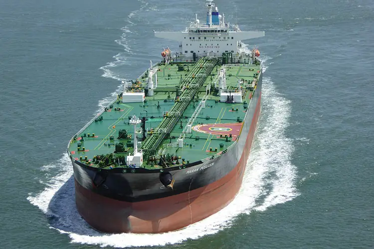
Inert Gas System (IGS) on a ship refers to a system deployed for the prevention of an explosion in the cargo tanks of a tanker. In this integrated system, while pumping out the liquid inflammable cargo, an inert gas (sometimes by flue gas from ship boilers) is also pumped in.
An oil tanker’s job is to carry different types of oil that vary in quality and these oils tend to produce vapors while they are being loaded for transportation. These vapors can be present even when there is no cargo on the ship. These vapors can cause severe and large-scale destruction if they come in contact with air that is rich in oxygen.
The resultant explosion can cause harm not just to human life and property since the explosion is occurring in the middle of the sea or ocean it can destroy marine life too. The smoke produced from the burning of such vapors causes air pollution.
This is where the Inert Gas System comes into play where it protects us from an explosion of such sort. This can be accomplished through an inert gas plant. The flue gas from the ship boiler can also be used for inerting.
The boiler flue gas is washed and cooled by the flue gas system and is delivered to the cargo tanks at the time of unloading and tank washing. This is enough because the flue gas already contains less than 5% of oxygen.
How Inert Gas System Works?
The basic functionality of the Inert Gas System is to suppress the combustion of hydrocarbon gases. Inert gases are used for this purpose because they contain less than 8% oxygen which is considerably less than what is required for burning. The job of the Inert Gas System is to spread the inert gas over the flammable one, the cargo oil and thereby increase the LEL (Lower Explosive Limit) and decrease the UEL (Upper Explosive Limit).
LEL represents the lower concentration at which the vapors can be ignited, and UEL represents the concentration at which the vapor explodes. All this is done to pull the concentration down to 10% which creates an atmosphere where the hydrocarbons inside the tank can no longer burn. The safety limit of inert gas is 5%.
All tanker ships use the Inert Gas System as a safety measure against explosion.
The Inert Gas System and its Components
Oil tankers use the following components in their IG system:
1) Exhaust gases source
The flue gas from the boiler or main engine exhaust is taken in as the inert gas source.
2) Inert gas isolation valve
It serves as the supply valve from uptake to the rest of the system isolating both the systems when not in use.
3) Scrubbing tower
A series of water sprays and baffle plates cool, clean, and moisten the flue gas entering from the bottom. This process reduces the SO2 levels up to 90% and the soot gets removed.
4) Demister
The moisture from the treated flue gas is absorbed demister. It is generally made of polypropylene.
5) Gas Blower
Generally, they are of two types. One is used for the IG operation and the other is used for topping up. For the former, a steam-driven turbine blower is used and for the latter, a blower running on electricity is used.
6) I.G pressure regulating valve
Based on the type of oil and its properties as well as the atmospheric pressure, the pressure within the tank changes. To keep this change under control as well as to prevent the blower fan from overheating a pressure valve is attached next to the blower discharge which sends back the excess air to the scrubbing tower.
7) Deck Seal
The deck seal prevents the gases from the blower from coming back to the cargo tanks. Usually wet type deck seals are used, and a demister is added to pull back the moisture from these gases.
8) Mechanical non-return valve
It is an added non-return mechanical device that is in line with the deck seal.
9) Deck isolating valve
This valve is used to isolate the engine room from the deck fully.
10) Pressure Vacuum (PV) breaker
The PV breaker helps to keep the unwanted change in the pressurization of the cargo in check. It consists of a vent that is fitted with a flame trap that prevents ignition during ongoing loading and discharging operations in the port.
11) Cargo tank isolating valves
A vessel has many cargo holds that are fitted with isolating valves whose operations are controlled by the most responsible officers onboard. The valves are used to control the flow of inert gas into the hold.
12) Mast riser
The job of the mast riser is to maintain a positive pressure of the inert gas when the cargo is being loaded. To avoid pressurization of the cargo tank at the time of loading the mast riser is kept open.
13) Safety and alarm system
It is obvious that a system in this complex will need its safety features to safeguard itself and its own machinery. This is achieved by the following alarm and automatic system shutdown mechanisms:
- If a certain level is reached in the scrubber an alarm goes off and the blower and scrubber tower gets shut down.
- The blower shuts down and the alarm is triggered when the scrubber tower experiences a low pressure in the seawater supply (0.7 bar approximately).
- When the deck seal experiences low pressure from seawater supply (approx. 1.5 bar) the alarm gets triggered and the blower shuts down.
- If the temperature of the inert gas goes beyond 70°C the alarm gets triggered and the system shuts down the blower.
- Low pressure in line after the blower (approx. 250mmWG) causes the alarm to get triggered and the blower to shut down.
- If the oxygen content exceeds 8% the alarm goes off and the gas delivery to the deck is halted.
- A low level in deck seal causes the alarm to go off. The blower gets shut down and so does the scrubber tower.
- An emergency stop also triggers the alarm and the blower, as well as the scrubber tower, is shut down.
In short, the alarms used in the system are:
- Scrubber low level
- Deck seal High level
- Low O2 Content (1%)
- High O2 Content (5%)
- Low lube oil pressure alarm
How the Inert Gas System Plant Works
The flue gas produced in the ship’s boiler is the basis of the production of the inert gas in the IG plant. The gas coming out of the boiler is extremely hot and is treated inside the inert gas plant where it is cleaned and cooled. After that, they are supplied to individuals’ tanks through PV valves and breakers. This ensures the proper safety of the tank structure and the atmosphere.
The system can be divided into two parts based on their function:
- A production plant that is responsible for the production and delivery of the inert gas with the help of blowers to the cargo tanks.
- A distribution system that controls the passage of the inert gas makes sure that the gas goes into the right cargo tank at the right time.
Working Procedure Of Inert Gas System in Brief
- The boiler gas is pulled into the scrubber through the flue gas isolating valves.
- In the scrubber unit, the gas undergoes the process of cooling, cleaning, and drying after which they are supplied to the tanks.
- The treated gas from the scrubber is then passed through the motor-driven blowers into the tanks. They are mounted on rubber vibration absorbers and isolated from the piping by rubber expansion bellows.
- The gas control valves regulate the quantity of gas to be delivered and the pressure controller manages the deck pressure. There is a set point below which, if the deck pressure falls, the output signal is raised to open the valve a bit further, and in the same way if the deck pressure rises the valve is closed to maintain the correct pressure. Thus, the system ensures that the circuit is neither overfed nor starved in the process with the help of the valves.
- The gas passes through the deck water seal, before entering the deck line, which doubles up as a non-return valve so as to stop the explosive gas from the cargo tanks.
- After passing the deck seal the inert gas is then mounted to create an equilibrium with the deck water seal pressure. Here the system gets shut down. If both the deck seal as well as the non-return valve fail, the relief valve vents the gases from the tank into the atmosphere.
- If during the process of separation of the ‘production’ and ‘distribution’ components the oxygen content of the gas rises above 8%, the oxygen analyzer detects it and triggers an alarm, and shuts down the plant.
